Tractive System Active Light (TSAL)
Intro to our tractive system
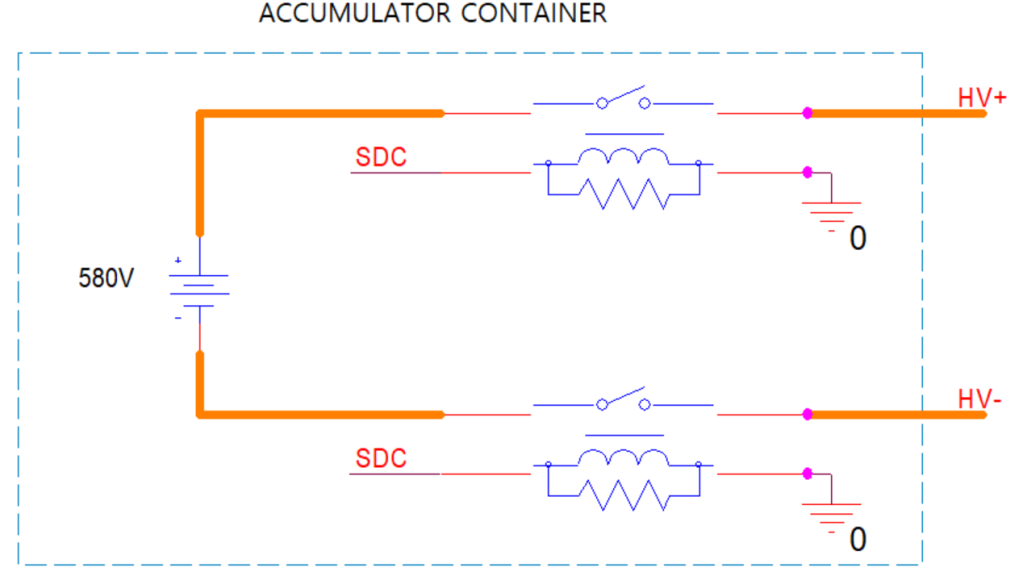
The Tractive System includes any components which are electrically connected to the high voltage battery (for example, the motor and its controller). The high voltage battery (or accumulator in FSAE terms) is electrically isolated from the rest of the system using 1 relay at each high voltage line (2 accumulator isolation relays in total).
These relays are energized via our shutdown circuit. Only when the shutdown circuit outputs a high signal, i.e. the vehicle is safe and controller status’ are OK, will the relays be energized and our accumulator connected to the motor controller.
The figure below shows an oversimplified schematic of our accumulator. When the tractive system is energized high voltage will be present at the HV+ and HV- lines.
The Tractive System Active Light (TSAL) is meant to indicate the status of the tractive system. If the tractive system is not energized, a stable green light will illuminate at the car’s roll hoop. If the tractive system is energized, a different light will flash red to alert those surrounding the car that high voltage is present outside the accumulator container.
So how does the TSAL circuit board know when there is high voltage present at the HV lines?
HV Sense Circuit

The LM311 is a comparator with an open collector output which is sinking if the negative input is greater than the positive input, and is high-Z when the relation between the inputs is reversed. The threshold for high voltage is 60 V, and a voltage divider is used at the inputs from the HV lines so that 60 V at the HV lines corresponds to 1.76 V at the LM311 positive input.
1.76 V is set as the reference point (at the negative input) using a voltage divider as well.
If the HV lines have a voltage 60 V then the LM311 is sinking and the optocoupler is on.
If the HV lines have a voltage 60V then the LM311 output is high-Z (neither connected to ground or voltage supply) and the optocoupler is off.
LED Drive
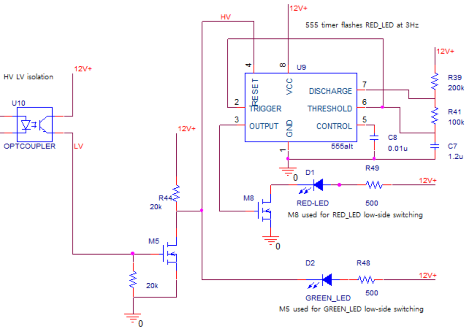
This optocoupler is used to isolate the high voltage and low voltage parts of the circuit. It also drives the NMOS M5 (as shown above). When low voltage is present at the HV lines, the LM311 is sinking, the optocoupler is on, and the NMOS is on. This NMOS is used for low-side switching of the green LED to indicate that no high voltage is present outside the accumulator container (in reality a connector is used on this PCB to connect the LEDs, which are mounted on the roll hoop, to the circuit).
How do we ensure that the red LED stays off in the “no-high-voltage” scenario?
The red LED is driven by the 555 timer for switching it at the desired frequency (which can be done by adjusting the values of the resistors and capacitors connected to the chip). The 555 timer will only provide an output signal if the “reset” input is high.
So, we connect the reset signal to M5, if no HV is present at the HV lines M5 will be on, connecting the reset signal to ground and ensuring that the 555 timer does not produce an output.
If HV is present at the HV lines, the M5 is off and the reset input is pulled up (connected to the circuit’s voltage supply).
Pull up and pull down resistors
Pull up resistors are used multiple times in this circuit, for example, at the 555 timer’s reset input.
How does the reset signal “choose” which state to be in (when it is connected to both the NMOS M5 and the pull up resistor R44)? If there is a connection to ground through the NMOS (low resistance) and a connection to the voltage supply through the 20kOhm R44 resistor at the same time, the reset signal will have a much closer value to ground or 0 V. This is because current always chooses the least resistive path to flow, which in this case is through the NMOS connection.
A pull up resistor is also used at the LM311’s output. The output is connected to the optocoupler’s cathode. If the cathode of the optocoupler’s diode is pulled up through the resistor, it will ensure that the optocoupler is off. If the LM311 is sinking, the cathode is connected to ground through a less resistive path. We basically use a pull up resistor to avoid having a high-Z connection at the cathode in the case where the LM311’s output is high-Z (as we are not sure what voltage value “high-Z” would be).
I would not have been able to design this circuit if it weren’t for the wonderful people who made these videos:
https://www.youtube.com/watch?v=bgW9xbbovIY&t=6s
https://www.youtube.com/watch?v=5dQUlfogNlM
Simulation
Low voltage at HV lines
I simulated the low voltage scenario by adding a 50 V DC source at the HV lines. Using PSpice’s current probes I measured the current flowing through the LEDs. After some adjustments to pull-up and pull-down resistor placements and values, I got the green LED to light up while the red LED is off.

LV scenario – 300 mA through green LED (will depend on LED’s current limiting resistor value)
High voltage at HV lines
To simulate the high voltage scenario, I placed a DC source with a value bigger than 60 V.

HV scenario – ~300 mA through red LED at a frequency of ~2 Hz
Final Board Design

This is the final board designed using OrCAD’s Allegro PCB Editor. This design will be sent to a PCB fab house so they can print the board for us.
