Fuse design
For our electric car, we are building a high voltage battery (or accumulator in FSAE terms) that consists of 690 cylindrical cells connected together. Our exact configuration is 5p138s (which means 5 cells connected in parallel first then 138 of those parallel blocks connected in series). As required by FSAE’s rules, we need to have cell level fusing for every cell/ string of cells connected in parallel. Since we have our cells connected in parallel first, this means that each one of our cells must have a fuse.
The fuse goes between our cell and the busbar which carries our accumulator current. The purpose of the fuse is to protect the battery pack in the scenario that a cell outputs more current than it should. For example, our cells (Samsung 30Q) are rated for a maximum current of 26.5 A for 5 secs. If the cell gives an output higher than this current level for too long, it could catch fire.
According to the recommendation of FSAE judges, a current rating approximately <2 times the maximum current output for the cells is a decent rating for a cell level fuse. We decided to have our fuses rated for just under 50 A.
FSAE’s rules also do not allow soldering as the cell-to-cell interconnection method, so we decided to go with spot welding as the most reliable yet affordable method for us. We decided to use Nickel to connect the cells in each 5-cell parallel group (via spot welding). We chose Nickel because it is relatively easy to spot weld. Even though it is not the most conductive, that is fine for connecting the cells in parallel since it won’t be the main current carrying path (the Nickel tab just equalizes the voltage across the parallel cells). The parallel groups will be connected together in series by bolting copper busbars to the Nickel tabs (the main current carrying conductor should have a high conductivity to reduce heat losses, so we chose copper).
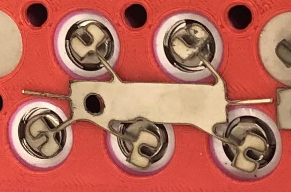
The picture below shows our final fuse design (the black residue is just due to the laser cutting of the Nickel tabs). The hole is where the copper busbar would be bolted. The thin strip between each cell and the wider part of the Nickel tab is the part that will act as our fuse.
As I mentioned above, we needed our fuses to blow at ~50A in under 5 seconds. We tested different fuse dimensions by varying the width and length of the fuse, keeping in mind that increasing the width of a conductor increases its ampacity but increasing length has the opposite effect. We tested different fuse sizes until, at a specific width and length, the fuse blew at our desired current level in the desired time. This was the final fuse design, and we continued testing that fuse at different current levels according to the FSAE fuse testing guidelines.
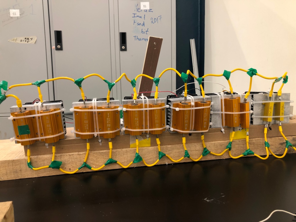
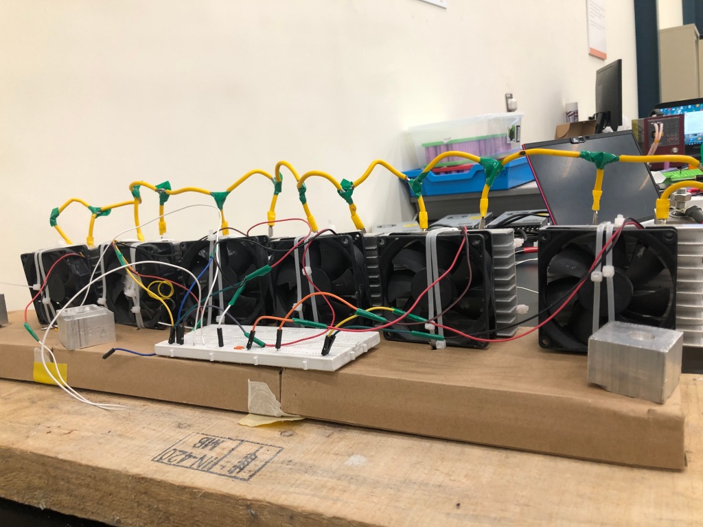
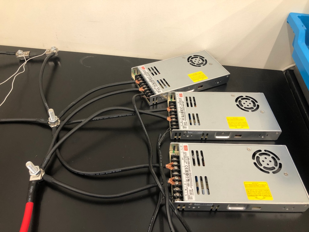
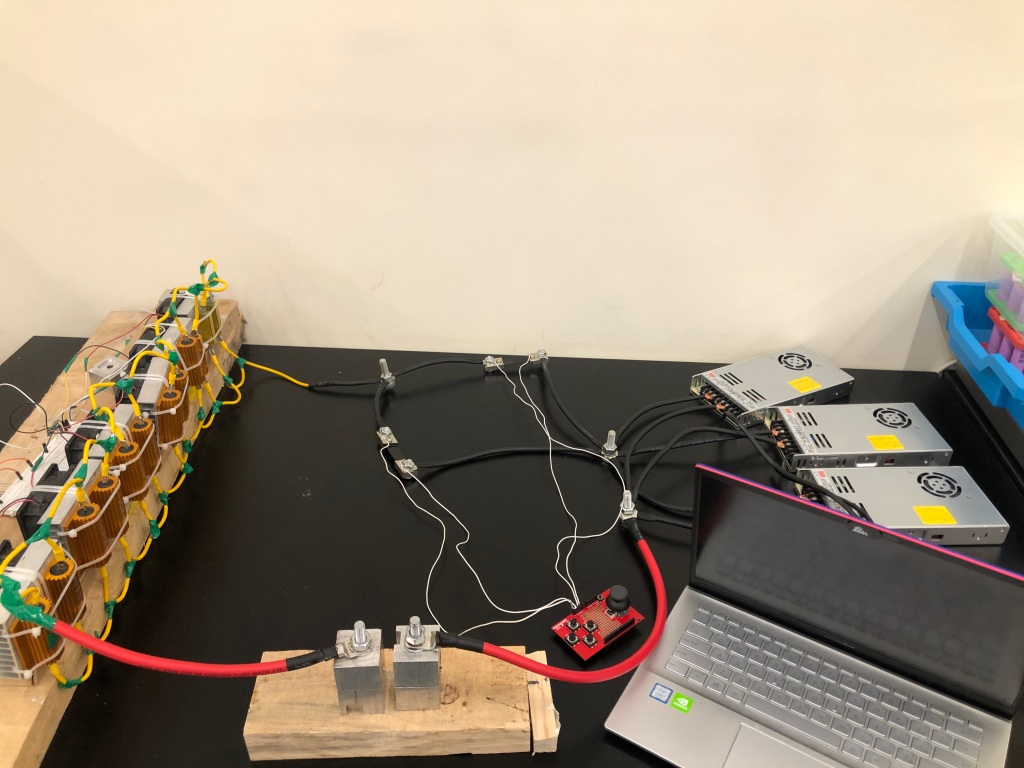
Fuse testing – load bank
To test our fuse we need to vary the current we were running through it up to ~200A. I built a resistive load bank by connecting low-resistance, high-power resistors in parallel and attaching them to heat sinks. I used constant voltage supplies (which means that they provide a constant voltage at the output as set by the user, but vary the current depending on the load) rated for up to 5V and 60A. by connecting 3 supplies in parallel, we could safely get up to 180A depending on the resistance of the load connected. I varied the resistance of the load bank by connecting or disconnecting resistors in parallel.