Shutdown circuit
The purpose of our shutdown circuit (SDC) is to energize our HV battery relays. The circuit includes several switches, and 3 power stages. Each power stage includes a DPST relay which is controlled by some controller/ safety circuit in the car. If any of these controllers/ circuits output a signal representing a fault, the respective relay will open, which opens the path from the low voltage (LV) supply to the high voltage (HV) battery’s relays (which will de-energize the relays). If there are no errors the relays will be closed, closing the path between the LV supply and the HV battery relays. The path from the LV supply and the HV battery relays (or the SDC output) is colored in green.
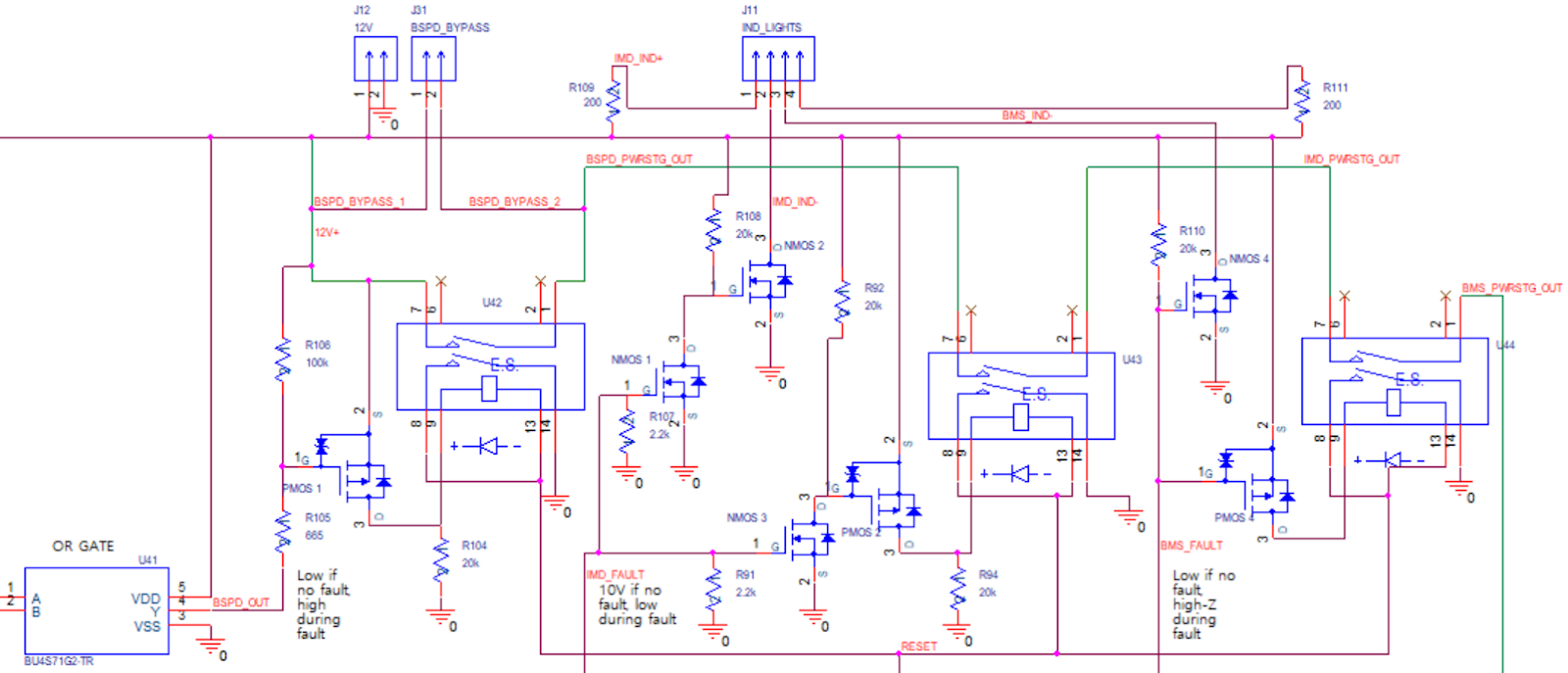
Brake system plausibility device (BSPD)
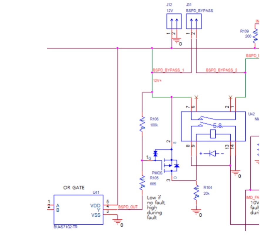
The first power stage is for the brake system plausibility device (BSPD), which should open the shutdown circuit if the brake pedal and accelerator are depressed at the same time.
A PMOS is used for high-side switching of the relay U42. if the BSPD output is high (fault condition) the PMOS should be off, switching off U42. If the BSPD output is low (no fault condition) the PMOS gate will be at a voltage level lower than the source, which should switch off the PMOS and switch off U42. R106 is used as a pull up resistor at the gate to ensure the PMOS default state is off.
R104 is used as a pull down resistor to ensure the relay default state is off.
In case the power stage is open, there is a reset button (non-latching) that must be pressed before the power stage can close again. Pin 13 of U42 (negative terminal of relay coil) is connected to the reset button, which if pressed will connect the pin to ground (not shown). If the power stage is open, the reset button must be pressed momentarily to energize the coil, this should close the contacts 8 and 14 which will ensure the negative terminal of the relay coil remains grounded even after the reset button is released.
Insulation Monitoring Device (IMD)
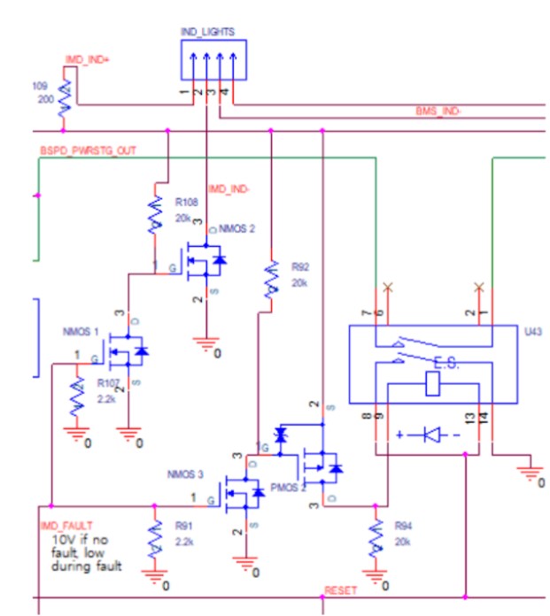
The insulation monitoring device monitors for isolation faults between our HV and LV systems. In case of a fault, the device outputs a low signal, which should switch off NMOS 3. The gate of PMOS 2 should then be pulled up through R92 which will switch the PMOS off. Pin 9 of U43 (the positive terminal of the relay coil) will be pulled down, ensuring the relay is open.
In case of a fault the IMD indicator light should also turn on. NMOS 1 will be off, so the gate of NMOS 2 will be pulled up ensuring that it turns on. NMOS 2 is used for low side switching of the LED, while R109 is used to limit the current.
The same reset button used for the BSPD is also used for the IMD power stage.
Battery Management System (BMS)
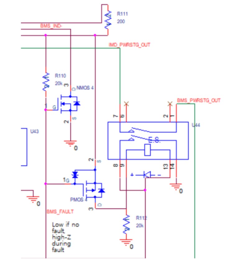
The BMS monitors for any issues with the HV battery. In case of a fault the output is high-Z, so the gate of PMOS 4 is pulled up through R110 switching the PMOS off. The positive terminal of the relay coil will be pulled down through R112, switching off the relay.
In case of a fault the BMS indicator light should also turn on. In case of a high-Z signal, the gate of NMOS 4 is pulled up, turning the NMOS on. NMOS 4 is used for low side switching of the LED, while R111 is used to limit the current.
The same reset button used for the BSPD and IMD is also used for the BMS power stage.
