Step 1: Create pinout sheets
My starting point for building the Low Voltage (LV) wiring harness was creating the pinout sheets for all the components in our race car. A pinout is a cross-reference between pins of an electrical connector or electronic component, and their functions. Every electrical connection has at least two end points, the first being the component we are creating the sheet for, and the second will be determined based on the function of each pin.
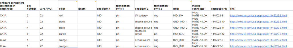
The pinout sheet in this screenshot is for an off-shelf component that we ordered, so the information in was mostly obtained from the datasheet of the device. I also made a label for each wire to make the manufacturing process easier and to help with debugging later. To avoid duplicates of the same wire in different pinout sheets, each label name is in the format <end point 1>_<end point 2>, and I ordered the end point names alphabetically. I also used different colors for the wires based on their function.
Subsystem schematics
For in-house built components, such as the high voltage battery, I first designed the internal schematic using OrCAD Capture to layout all the low voltage connections inside the battery container, and then decided on the external connections that were needed. For a simpler and neater harness, I grouped connections going to the same component/ area in the car in the same connector, or placed those connectors physically closer to each other on the container.
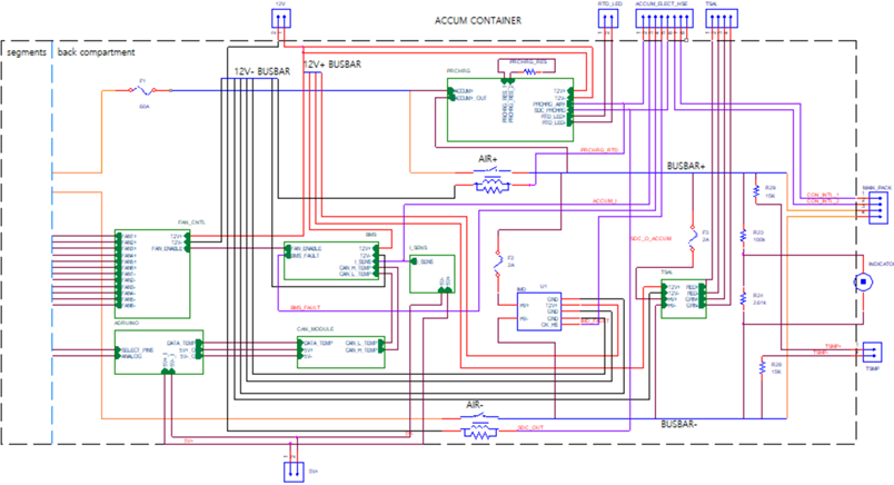
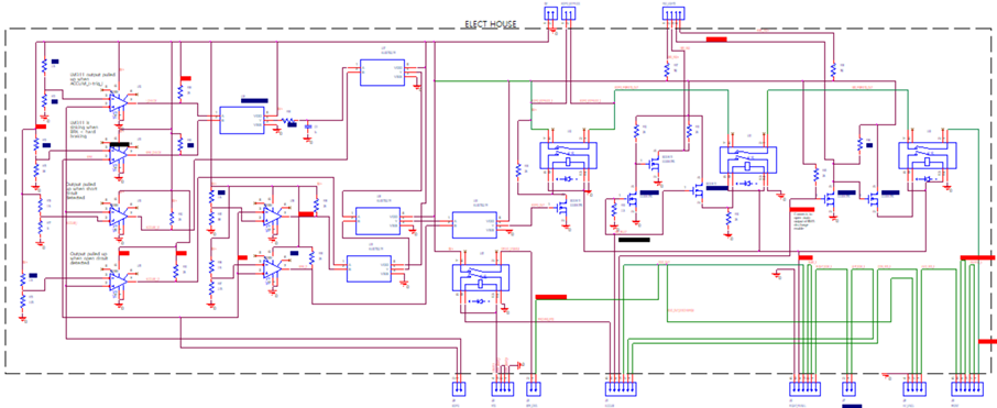
Using this schematic I created a pinout sheet for the battery. I repeated the same process to make the pinout of our electronics house, which houses our safety shutdown circuits.
Full LV system schematic
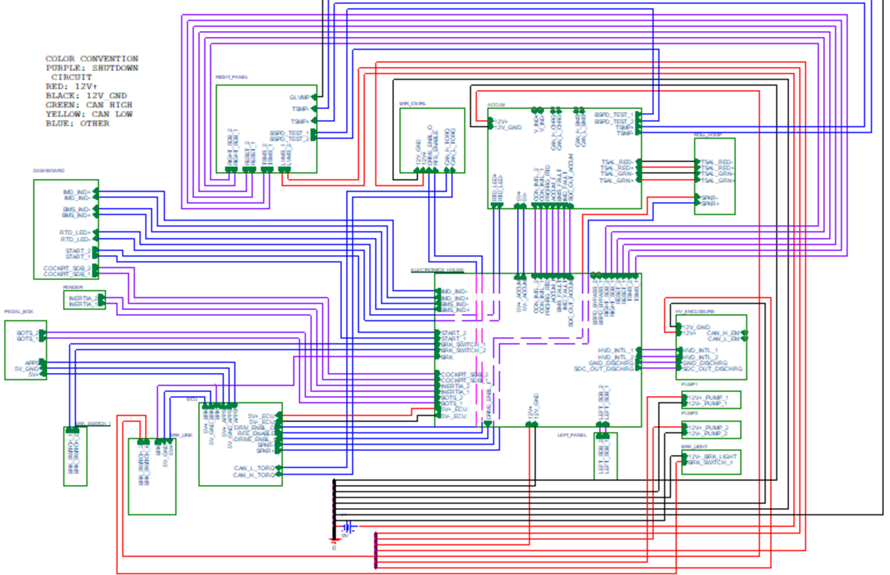
After making schematics and pinout sheets for all the components, I made a high level schematic showing all the connections in the LV system. This was used as to give me an idea of the best way to route the wires along the chassis.
Step 2: Measure wire lengths
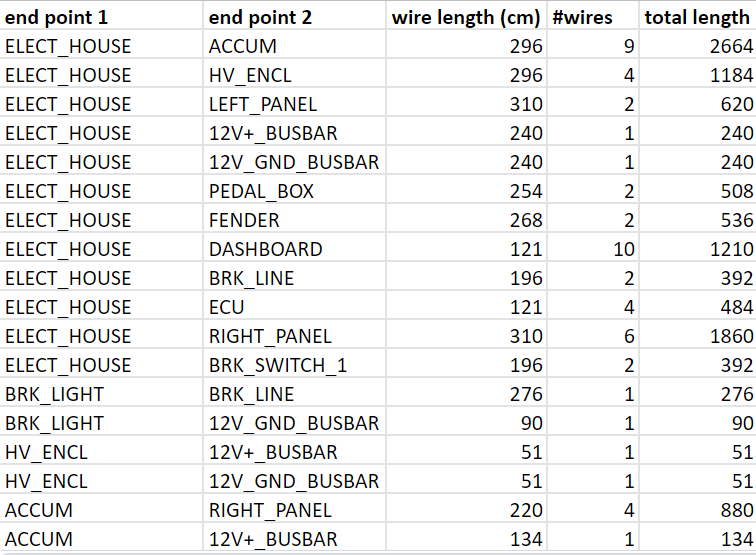
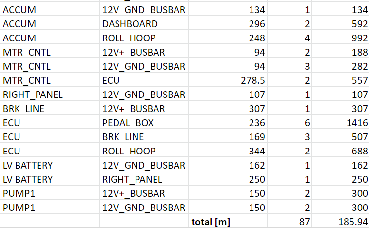
In each pinout sheet there is a column for wire length, which is initially left empty. To measure wire lengths some teams develop a CAD model of their wiring harness, but we already had our chassis built at this point, so we we used that to take our measurements.
The process was as follows: we first measured the length of the wires needed from each component to any other component that it will have connections to. For example, there are 9 wires from the electronics house to the HV battery. We routed a wire along the chassis frame between the points where those two components will be placed. Then, we measured the length of this wire and used that value for the length of any wire between those the two components (the rest of the 8 wires were later cut on a table which is easier than measuring along the chassis frame again).
Step 3: Inventory
Wires
I used the sheet above to calculate the total length of wire needed for the whole harness, which helped me estimate how much we needed to buy.
Connectors
I decided to go with the Amphenol AT Series connectors because they had the variety of connectors that we needed with good IP rating, but were cheaper than the Deutsch DT connectors. Using the schematics and pinout sheets I made, I calculated the number of 2 pin, 4, pin, 6 pin and 8 pin connectors we needed. I also calculated how many connectors we would need for the connections that would change during charging. I made sure to order connectors and crimps with their mating parts.
Tools and accessories
Tools we needed were a wire cutter, stripper and crimper for the gauge that we were working with, and a label maker. We used twist ties to initially hold wires in place on the frame while routing, and zip lock bags to categorize the wires after they were cut.
Step 4: Cutting, routing, labelling and twisting
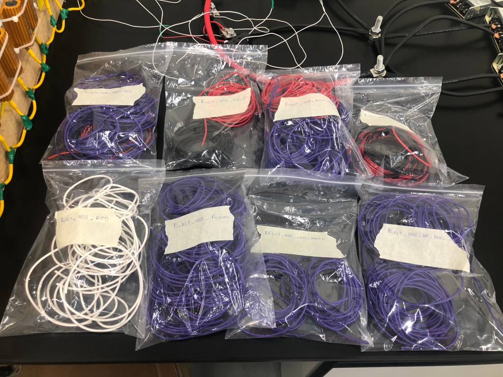
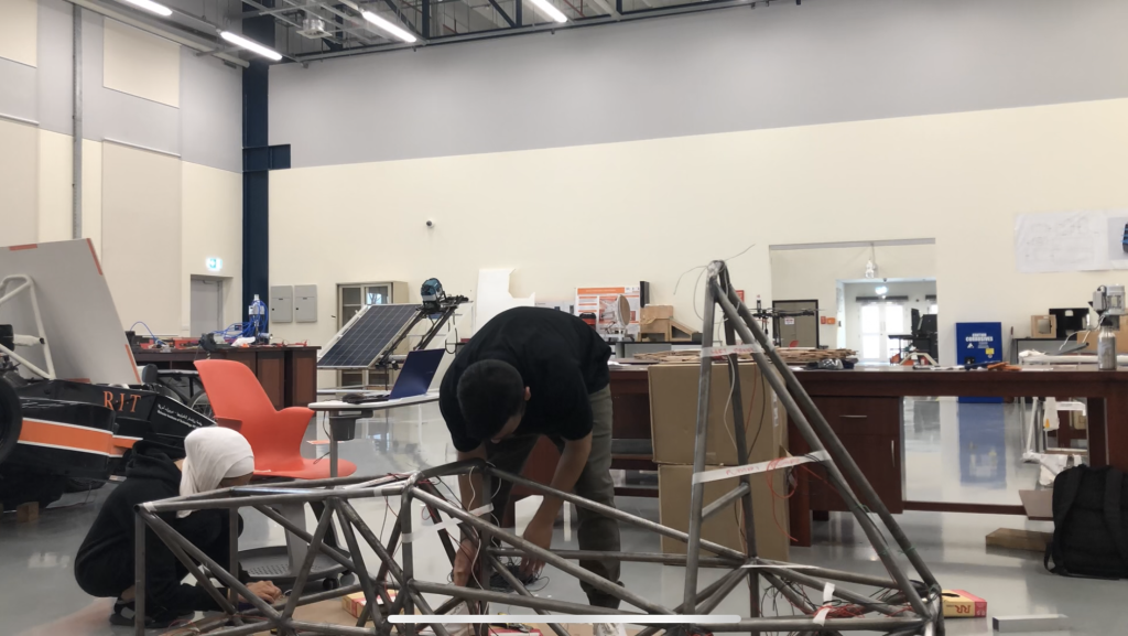
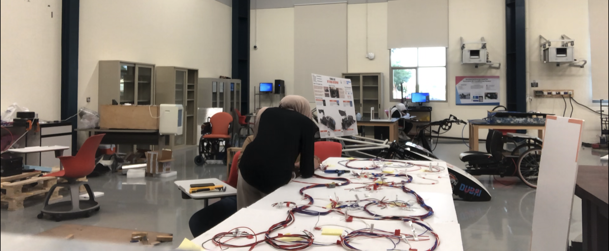
We stuck white foam boards onto two benches that we put together in our work station for a clean surface to lay out and measure our wires on. We grouped the cut wires for each of the components into zip lock bags.
Then, we routed each wire onto the chassis frame. We used twist ties to attach the wires to the frame during this process.
After routing we realized that we forgot to label the wires, so we had to use the continuity test on a multimeter to find out which wire was which on both ends. I definitely would advise labelling your wires before categorizing them into the zip locks.
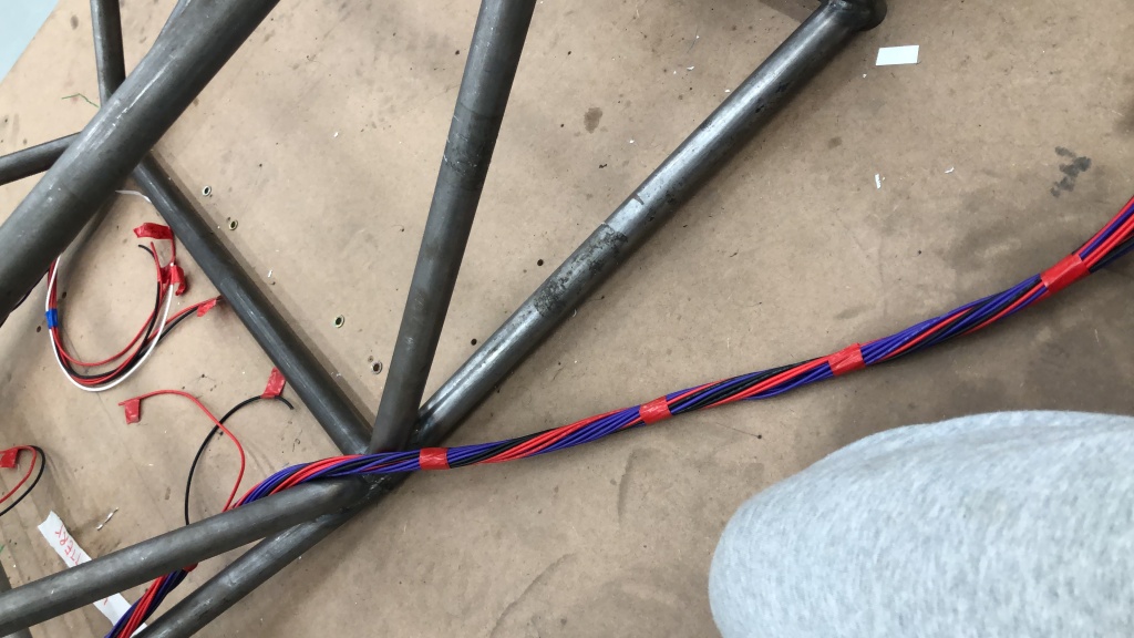
Next, I twisted the wires and taped them every few inches. Twisting the wires helps with strain relief and makes the harness much neater.
Step 5: Assembling connectors
Finally, we installed the connectors onto the wires. We practiced stripping and crimping onto some wire scraps first before starting with the harness.
Step 6: Heat shrink and wire sheath
Sadly, we never made it to this stage, but the next steps would have been to apply heat shrink where necessary, such as at the base of the connectors, and then cover the harness with some sort or wire sheath or sleeve.
